
Pipe Hanger Spacing Guide for HVAC & Plumbing
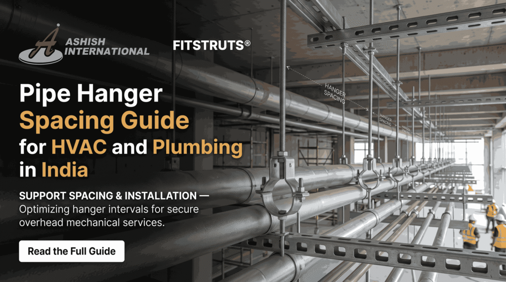
A pipe hanger spacing guide for HVAC and plumbing in India sets how far apart supports should sit so a pipe does not sag, stress, or leak. As a general rule, horizontal steel pipe up to 1.5 inches needs a hanger about every 2.1 metres (7 feet), 2 to 6 inch pipe every 3 metres (10 feet), and larger pipe every 3.7 metres (12 feet). Copper tubing needs closer support, roughly 1.8 metres (6 feet) for small sizes and up to 3 metres (10 feet) for larger. Vertical pipes are supported at each floor level with riser clamps. Spacing tightens for heavier pipe, water-filled lines, and cast iron. These intervals follow global standards like MSS SP-58 and SP-69. Ashish International, with 25+ years in MEP supports, manufactures pipe hangers and support systems built to these standards, and this guide gives the spacing tables and the rules behind them. Why Correct Spacing Matters More Than It Looks Hanger spacing is easy to treat as a rough guess, but getting it wrong causes real, expensive problems. A pipe supported too far apart sags between hangers, and that sag does three things at once: it pools liquid and traps air, it puts bending stress on the pipe and its joints, and over time it can crack a fitting or spring a leak. Space hangers too close and you waste material and labour on a job that did not need it. Correct spacing keeps the pipe straight, drains it properly, and spreads the weight evenly onto the structure. Standards like MSS SP-69 exist precisely because guessing these intervals leads to failures that are costly to fix after the ceiling is closed. Treat spacing as an engineered number rather than a guess and a piping run stays sound for its full life. Maximum Hanger Spacing Table The table below gives typical maximum horizontal spacing for water-filled steel and copper pipe, converted to metric for Indian sites. Use it as a starting point, then check the load for your exact line. Pipe size Steel pipe spacing Copper pipe spacing Up to 1″ ~2.1 m (7 ft) ~1.5 m (5 ft) 1.25″–1.5″ ~2.1 m (7 ft) ~1.8 m (6 ft) 2″–2.5″ ~3.0 m (10 ft) ~2.4 m (8 ft) 3″–6″ ~3.0 m (10 ft) ~3.0 m (10 ft) Larger than 6″ ~3.7 m (12 ft) ~3.0 m (10 ft) Two rules sit alongside this table: copper always needs closer support than steel of the same size because it is softer, and every run needs an extra hanger within about 600 mm (2 feet) of each elbow, tee, or valve. Read the table for your pipe material and size and a correctly supported run starts there. What Makes Spacing Tighter The table gives a baseline, but several real-world factors shorten the safe interval. Watch for these: Pipe material: copper and plastic sag more than steel and need closer support; cast iron needs the closest. Contents: a water-filled or fluid-carrying line is far heavier than an empty one, cutting the safe span. Insulation weight: lagging adds load that the hangers must carry. Temperature: hot lines expand and need supports that allow movement without over-stressing. Concentrated loads: valves, strainers, and fittings add point loads that need their own support. Contents is the factor most often missed: sizing spacing for an empty pipe and then filling it with water is a common way to overload hangers. Adjust the interval for material, weight, and fittings and a table figure becomes a safe real-world span. How Vertical Pipes Are Different Vertical runs follow a completely different rule from horizontal ones, and mixing them up is a common error. A horizontal pipe is supported against sagging, so spacing is about deflection. A vertical pipe, or riser, is supported against its own weight pulling straight down, so it is held at each floor level rather than at a fixed distance, typically with a riser clamp resting on the floor slab. The Rules for Risers For vertical pipe, three points govern the support. First, support the riser at every floor penetration so each floor carries one section’s weight. Second, provide at least two supports on any vertical run within a space, never just one. Third, use a proper riser clamp, not a horizontal pipe clamp, because a standard clamp holds by friction and can slip under vertical load. Support risers by floor level, with the right clamp, and a tall run stays safe in a multi-floor building. How to Apply This on Your Project Turning these rules into a real support layout is a short, ordered process: List each line: note pipe material, size, and whether it runs horizontal or vertical. Read the base spacing: take the interval from the table for that material and size. Adjust for load: shorten the span for water-filled, insulated, or heavy pipe. Add fitting supports: place a hanger within 600 mm of every elbow, tee, and valve. Pick the support and finish: match pipe clamp supports, strut channel, threaded rod, and beam clamps in a finish that suits the environment. Layouts most often go wrong at step three, because base tables assume a standard condition your line may not match. Apply the table and then adjust for the real load, and the result is a support plan that holds, the backbone of any well-built MEP support structure. Hangers Made for the Loads You Design To A spacing table is only useful if the hanger at each point actually carries its share, so the hanger itself has to be made to a dependable rating. Ashish International backs that with 25+ years of manufacturing across three units and 60,000 square feet, at 350 tonnes a month under in-house quality control, so pipe hangers and clamps hold consistent load ratings across a whole run. MEP contractors, stockists, and sourcing companies across the UK, Europe, the Middle-East, Australia, and Africa specify us for that reliability, and several have partnered with us for over 20 years, some under NDA for their own designs. We
Strut Channel for Pre-Engineered Buildings in India
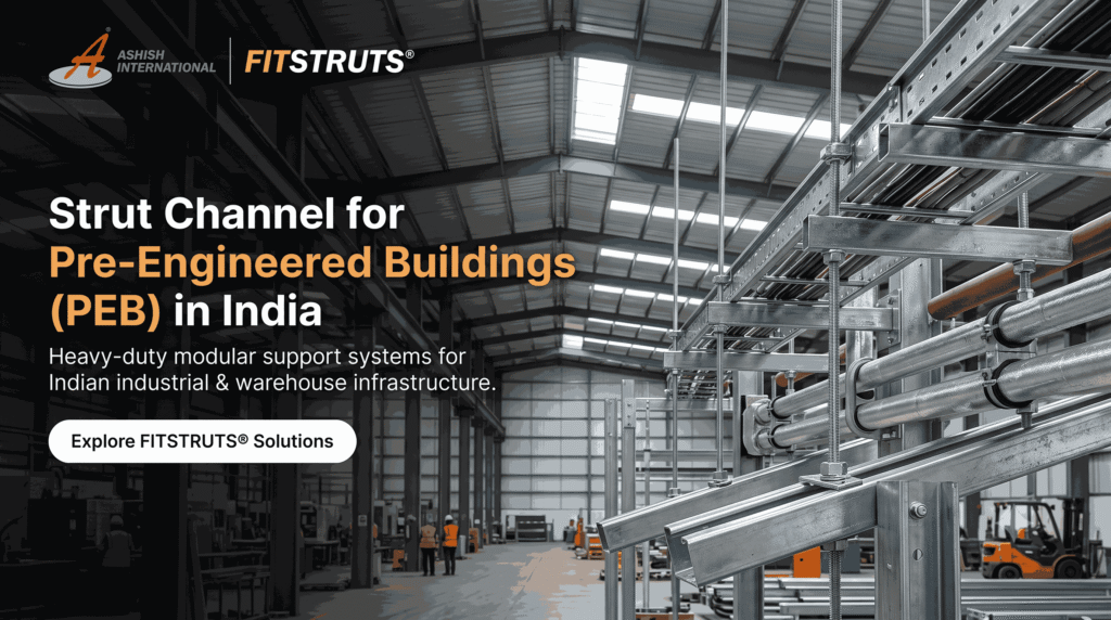
Strut channel for a pre-engineered building (PEB) in India is the framing system that holds up pipes, cable, and ducts inside steel-framed warehouses, factories, and industrial sheds. A PEB is built from steel portal frames rather than concrete, so its MEP support works differently: instead of drilling anchors into a slab, strut channel fixes to the steel frames and purlins with beam clamps, forming trapezes and brackets across wide, high spaces. PEBs have long clear spans and tall roofs, so support runs are long and heights are large, making a strong, adaptable channel system essential. The core parts are strut channel for framing, beam clamps to grip the steel, threaded rod for drops, and pipe and cable clamps. Ashish International, with 25+ years in MEP supports, manufactures strut channel and fittings suited to PEB structures, supplied across India and worldwide. Why MEP Support in a PEB Works Differently A pre-engineered building changes how services are supported, because there is no concrete to fix into the structure is steel. That single fact drives several differences: Fix to steel, not concrete — support clamps onto portal frames and purlins with beam clamps, so no drilling or anchor bolts into a slab. Long clear spans — PEBs span wide without internal columns, so support runs are long and need well-planned drops. Tall roof heights — services hang from high frames, so trapezes and rods are longer and must stay stable. Adaptable layout — factories and warehouses change use, so support must be easy to move and extend. Bare steel exposure — big sheds are often unconditioned, so corrosion protection matters. Fixing to steel rather than concrete is the defining difference, and it makes beam clamps and channel the natural support method. Design PEB support around the steel frame, not a slab, and the whole system fits the building. How Support Fixes to the Steel Frame In a PEB, the steel frame is both the structure and the fixing point, and strut channel is what turns it into a support system. A beam clamp grips the flange of a portal frame or purlin with no drilling, and a threaded rod drops from it to a strut-channel trapeze below, which then carries the pipes, cable trays, or ducts. Because nothing is drilled, the support can be repositioned as the building’s use changes a real advantage in a warehouse or factory that gets re-laid-out over its life. For long spans, a back-to-back strut channel or deeper section keeps trapezes rigid between widely spaced frames. Build the support off the steel frame with clamps and channel, and a PEB gains a services layout that is both strong and easy to change. What Support Carries in a PEB Different services in a steel building need different support, and the table below maps the main ones to the right approach. Service Typical support Key concern Electrical cable and containment Channel trapezes, cable tray Long spans, high routing Process and utility pipe Trapeze hangers, pipe clamps Weight, long drops Fire-fighting pipe Braced trapeze and riser Code, water weight HVAC ducts Trapeze from purlins Width, span between frames Lighting and services drops Channel brackets, rod Height, adjustability Long spans and tall drops shape almost every choice, which is why PEB support leans heavily on trapezes carried from the steel frame. These are the demanding conditions our MEP support structures are built for. Match each service to a frame-fixed support method and a big shed’s services stay secure across every span. How to Specify PEB Support Specifying support for a steel building is an ordered process, and getting it right avoids costly rework at height: Map the frame layout — note portal-frame and purlin positions, since these are your fixing points. Plan the drops — set trapeze positions to span between frames without over-long unsupported runs. Size the channel and rod — match to the combined service load and the span between fixings. Choose beam clamps — select beam clamps rated for the flange size and load. Match the finish — corrosion protection to suit an often-unconditioned shed environment. Frame layout drives step one, because in a PEB your fixing points are set by the steel, not chosen freely like slab anchors. Plan the support around the frame grid and a services layout goes up fast and stays adjustable. Materials and Finishes for Shed Environments Big industrial sheds are often unconditioned — open to heat, humidity, and dust — so finish matters more than in a sealed building: Hot dip galvanised — the practical default for most warehouses and factories, giving strong corrosion life. Pre-galvanised — cost-effective for dry, sheltered internal runs. Stainless steel — for chemical plants, coastal sheds, or humid process areas. Match every fitting to the channel’s finish, since a plain-steel clamp on a galvanised channel rusts first and weakens the run. Choose the finish for the real shed environment and support lasts the building’s full life. Support Made for Big Steel Buildings A PEB goes up fast and gets re-laid-out often so its support has to be quick to install, easy to move, and made to a dependable standard across long runs. That is where manufacturing depth counts: Ashish International brings 25+ years across three units and 60,000 square feet, producing 350 tonnes of MEP support a month under in-house quality control, so channel, clamps, and rod hold consistent fit and rating over an entire shed. PEB builders, industrial contractors, stockists, and sourcing companies across the UK, Europe, the Middle-East, Australia, and Africa specify us for that consistency, and several have partnered with us for over 20 years, some under NDA for their own designs. We manufacture to the dimensional and load standards global specifiers expect, and for brands and MNCs we run the full range as white-label your spec, your branding, with FITSTRUTS® where a stock line fits. For load data, product details, or a white-label discussion, call +91-99888-54380 or email ashishint2001@gmail.com. Frequently Asked Questions Q1. What is strut channel used for in a pre-engineered building?
Anchor Bolt Installation Mistakes in Concrete
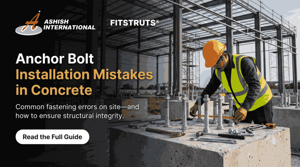
The most common anchor bolt installation mistakes in concrete are a dirty drill hole, wrong embedment depth, over- or under-tightening the bolt, and setting it too close to an edge. Any one of these can cut a bolt’s holding power by half or more, even when the bolt itself is the right size and grade. A hole left full of drilling dust is the single biggest cause of anchor bolt pull-out, because the dust stops the bolt or adhesive gripping the concrete. Getting the torque wrong comes next: too little and the bolt never sets; too much and it strips the concrete or snaps. A strong bolt fails when it is installed carelessly. Ashish International, with 25+ years in industrial fasteners, supplies anchor bolts with clear installation data, and this guide covers the mistakes that cause failure and how to avoid each one. The Seven Mistakes That Cause Most Failures Nearly every anchor failure traces back to a short list of avoidable errors. Ranked by how often they cause trouble on site: Not cleaning the hole — drilling dust left in the hole is the top cause of pull-out; the bolt grips dust, not concrete. Wrong hole diameter — too wide and the bolt cannot expand or bond properly. Shallow embedment — a bolt set too shallow loses most of its pull-out strength. Bad edge distance — set too near an edge, the concrete breaks out in a cone before the bolt fails. Wrong torque — under-tightening leaves it loose; over-tightening strips or snaps it. Ignoring cracked concrete — using non-cracked load figures where the concrete is cracked over-estimates capacity. Mismatched fastener — using the wrong anchor type for the base material or load. That first mistake alone accounts for a large share of field failures, and it takes seconds to fix with a blow pump and brush. Knowing these seven is the starting point for a fixing that holds for its full design life. Why a Correctly Sized Bolt Still Pulls Out It surprises many people that a bolt of the right size and grade can still fail, but installation, not specification, is usually to blame. When an anchor bolt pulls out, the concrete around it has given way rather than the steel breaking and that almost always comes from a dirty hole, shallow embedment, or an edge too close. A hole full of dust can lose a major share of its rated pull-out strength, because the bond or expansion never fully engages. Shallow embedment has the same effect, since pull-out resistance depends heavily on how deep the bolt sits. This is why our wedge anchor and foundation and anchor bolts ship with embedment and hole-size data printed clearly. Once you see that failure usually starts in the concrete, not the bolt, attention shifts to careful installation. Getting the Torque Right Torque is where good bolts are quietly ruined, because both too little and too much cause failure. Each bolt size has a recommended installation torque, and staying near it is what lets the bolt set correctly without damaging the concrete. The table below gives typical recommended torque ranges for common sizes. Size Typical torque What goes wrong if ignored M8 ~20 Nm Loose set or stripped thread M10 ~40 Nm Under-torque leaves it loose M12 ~60 Nm Over-torque cracks the concrete M16 ~80 Nm Snapped bolt or spalled concrete M20 ~150 Nm+ Severe over-torque splits the slab The safest practice is a calibrated torque wrench, not a feel-based tighten with an impact gun, which is a common way to over-torque without realising. These are general figures always follow the exact torque for your specific wedge anchor fastener or pin-type anchor. Torque to spec rather than by feel and a bolt stays tight without breaking what holds it. The Cracked-Concrete Trap One error deserves its own mention because it hides in the paperwork, not the workmanship. Load tables usually quote figures for non-cracked concrete, but slab edges, tension zones, and seismic areas are often cracked and there the same bolt holds noticeably less, sometimes a third lower. Using a non-cracked figure in cracked concrete looks fine on paper yet leaves a fixing badly under-strength. Confirm the concrete condition and use the matching load column before finalising a size. How to Install an Anchor Bolt That Holds Avoiding failure is mostly about a few disciplined habits, and none of them are difficult: Clean the hole properly — blow out dust, brush the walls, and blow again before setting the bolt. Drill the right hole — match the drill diameter and depth to the bolt’s data sheet. Hit the embedment — set the bolt to the full stated depth, not just flush. Respect edge and spacing — keep clear of edges and other bolts per the load table. Torque to spec — use a calibrated wrench and the recommended value for the size. These steps take minutes and cost nothing, yet they separate a fixing that holds for decades from one that pulls out under load. The same discipline underpins the reliable MEP support structures and threaded rod fixings we supply. Install with care rather than just quickly, and an anchor becomes genuinely dependable. Bolts and Data That Set Installers Up to Succeed Half of a good fixing is the installer’s care the other half is a bolt made right, with the data to install it correctly. That is what 25+ years of fastener manufacturing delivers: Ashish International runs three units over 60,000 square feet at 350 tonnes a month under in-house quality control, shipping anchors with clear embedment, hole-size, and torque data so crews avoid the mistakes above from the start. Contractors, stockists, and sourcing companies across the UK, Europe, the Middle-East, Australia, and Africa rely on that consistency, and several have partnered with us for over 20 years, some under NDA for their own designs. We manufacture anchors and industrial fasteners to the standards global specifiers expect, and for brands and MNCs we run the full range as
Riser Clamp vs Pipe Clamp for Vertical Pipe
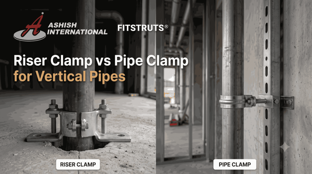
In the choice of riser clamp vs pipe clamp for vertical pipe, the riser clamp is the correct one: a standard pipe clamp is built for horizontal runs and will slip under a vertical load. A riser clamp wraps around a vertical pipe and rests its two arms on a floor slab or structural steel at each floor penetration, so the pipe’s full weight transfers safely to the building. A standard pipe clamp or U-bolt holds a pipe sideways by friction alone and is not rated to carry weight along the pipe’s axis, so on a riser it can slowly slide until the whole run drops onto the bend below. Use a riser clamp for any vertical pipe, and a pipe clamp for horizontal runs. Ashish International, with 25+ years in MEP supports, manufactures both riser clamps and pipe clamps to international standards, and this guide explains exactly when to use each. The Core Difference in One Idea The whole distinction comes down to the direction of the load, and getting this one idea right prevents the most dangerous support failure in plumbing. A horizontal pipe pushes down on its support, so a standard clamp holding it from above or the side works well. A vertical pipe pushes along its own length, straight down through itself, which no sideways clamp can hold by friction for long. A riser clamp is designed for exactly this axial load: its arms sit on a solid surface and carry the pipe’s weight in compression, not friction. Using a horizontal clamp on a vertical pipe is the single most common, and most hazardous, mistake in pipe support, because it fails slowly and then all at once. Once you see that load direction, not pipe size, decides the clamp, every correct choice follows. Riser Clamp vs Pipe Clamp, Side by Side The two devices look similar but do very different jobs. The table below sets out how they compare for vertical pipe support. Feature Riser Clamp Standard Pipe Clamp Load direction Vertical / axial Horizontal / lateral How it holds Arms rest on slab or steel Friction around the pipe Where it sits At floor penetrations Along horizontal runs Rated for riser weight Yes No, will slip Typical use Multi-floor risers Horizontal mains and branches Failure risk if misused None when correctly specified Pipe slides and drops The decisive row is “rated for riser weight”: a standard clamp simply is not, which is why it should never carry a vertical run. Read this comparison first and the choice is settled before any sizing begins. When to Use Each One Matching the clamp to the run is straightforward once load direction is clear. Use each where it belongs: Use a riser clamp: on any vertical pipe passing through floors, especially heavy water-filled or cast-iron risers in multi-floor buildings. Use a pipe clamp: on horizontal mains, branches, and short runs where the load presses down on the support. Support cast iron more often: heavier pipe materials need closer support intervals on the riser. Distribute tall risers: a very tall or heavy riser may need clamps at several floors so no single slab is overloaded. The clearest rule for a vertical pipe support in India is simple: if the pipe goes up through a floor, it needs a riser clamp, not a pipe clamp. Choose by load direction rather than habit, and a riser stays safe for the life of the building. How a Riser Clamp Actually Carries the Load Understanding the mechanism explains why the riser clamp is trusted for heavy vertical runs. The clamp is fitted around the pipe and its bolts tightened so the inner surface grips firmly: full surface-to-surface contact is what stops slippage, which is why set-screw-only clamps are not used on risers. The two arms then extend past the floor opening and rest on the slab, transferring the pipe’s weight straight into the structure in compression. For very heavy risers, shear lugs are sometimes welded to the pipe so the load bears on them rather than on friction alone. Two-Bolt vs Yoke Clamps There are two common riser clamp types, and the choice depends on load. A two-bolt riser clamp suits standard vertical runs and is the everyday choice. A yoke clamp carries a greater load and keeps a lower profile below the pipe, which helps where clearance is tight. For the heaviest risers, the yoke design is the safer specification. Match the clamp type to the riser’s weight and the arms and bolts are never over-stressed. How to Specify the Right Support Selecting the correct clamp is a short, ordered check. Work through it in this order: Identify the run: vertical or horizontal decides riser clamp or pipe clamp. Size to the pipe: match the clamp to the exact pipe outer diameter. Account for the contents: water-filled and cast-iron pipe are far heavier than empty. Set the intervals: support the riser at each floor, more often for heavy material. Match the finish: galvanised or stainless to suit the environment, with matched threaded rod and fixings. Get step one right and it prevents the dangerous mistake of a pipe clamp on a riser, where most vertical-support failures begin. These clamps work alongside strut channel, pipe hangers, and beam clamps in a full support system. Specify by run type and pipe weight and a vertical support becomes genuinely reliable. Clamps Rated for the Weight They Carry A riser clamp holds a live, water-filled pipe several storeys tall, so its arms, bolts, and grip have to be made to a real rating, not just a shape. That is where manufacturing depth counts: Ashish International brings 25+ years across three units and 60,000 square feet, producing 350 tonnes of MEP support a month under in-house quality control, so every clamp performs to spec. Plumbing and MEP contractors, stockists, and sourcing companies across the UK, Europe, the Middle-East, Australia, and Africa buy from us for that assurance, and several have worked with us for over 20
Strut Channel & MEP Support for Hospitals in India
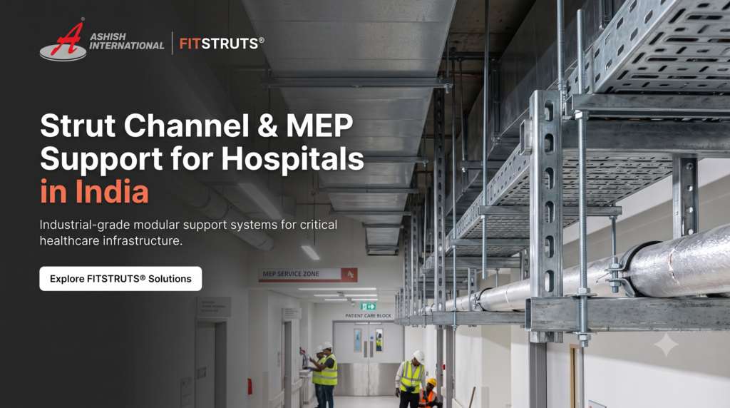
Strut channel and MEP support for a hospital building in India is the framing and fixing system that holds up the pipes, medical gas lines, cables, and ducts running through a healthcare facility built to keep them clean, secure, and safe during any emergency. A hospital is not an ordinary building: its supports must resist corrosion and infection risk, survive an earthquake so life-support services keep running, and carry critical systems like medical gas and fire pipe without fail. That is why hospital MEP support uses corrosion-resistant channel, hygienic infection-control design, and seismic bracing keyed to standards like NABH and the national building code. The core parts are strut channel for framing, seismic braces, medical-gas and pipe clamps, and rated anchors. Because a failure can risk patient lives, every support must be engineered to its role. Ashish International, with 25+ years in MEP supports, produces strut channel and support systems for hospital projects, supplied across India and worldwide. Why Hospital Support Is Held to a Higher Standard A hospital carries services that other buildings simply do not, and its support system reflects that. The higher standard comes from several demands at once: Life-critical services — medical gas, vacuum, and fire pipe must stay supported even in an emergency. Infection control — supports in clinical areas must be cleanable and corrosion-free, harbouring no bacteria. Seismic safety — bracing must keep services intact during an earthquake so care can continue. Continuous operation — a hospital never closes, so supports must be reliable for decades without disruption. Code and accreditation — NABH and the national building code set requirements support must meet. What defines hospital support is that failure risks patients, not just property. Engineer support to keep critical services running through any event and it is fit for a healthcare facility. Supporting the Critical Services Different hospital services need different support, and the table below maps the main ones to the right approach. Service Typical support Key concern Medical gas and vacuum pipe Clean pipe clamps, channel Purity, no contamination, security Fire-fighting pipe Braced riser and trapeze Must survive seismic events HVAC ducts and chilled water Trapeze hangers Weight, infection control Electrical and data cable Channel and tray supports Routing, backup-power continuity Plumbing risers Riser clamps at each floor Vertical load, multi-floor buildings Medical gas most defines a hospital, where clean, secure support is a patient-safety matter, not just an engineering one. Match each critical service to properly engineered support and a hospital runs safely around the clock. Infection Control and Seismic Safety Together Two demands set hospital support apart from every other building, and both must be designed in from the start. Infection control means supports in clinical and sterile areas use corrosion-free stainless steel channel with smooth, cleanable, crevice-free design no rust, no bacteria traps, no shedding particles near patients. Seismic safety means the support system is braced so that pipes, gas lines, and ducts stay in place during an earthquake, keeping life-support services connected when they are needed most. Why Both Matter at Once In a hospital these two are not separate boxes to tick a clinical area needs a support that is both hygienic and seismically braced. A back-to-back strut channel or braced frame handles the seismic load, while a stainless finish and clean design handle infection control, and the two are engineered into the same assembly. Design for hygiene and earthquake safety together, not one at a time, and a hospital support is genuinely fit for its role. How to Specify Hospital MEP Support Specifying support for a healthcare facility is an ordered process, and getting it right protects both patients and compliance: Classify the area — clinical, sterile, service corridor, or plant room sets the hygiene grade. Identify critical services — medical gas, fire, and life-support runs need the most secure support. Design the seismic bracing — brace risers, trapezes, and heavy runs to the applicable code. Choose infection-control finishes — stainless and clean design for clinical zones. Match every fitting — spring channel nuts, threaded rod, and clamps in the same corrosion grade. Hospital support most differs from ordinary work at step three, because seismic bracing is a life-safety requirement, not an optional extra. Specify by area, service, and seismic need and the result is support a healthcare facility can rely on. Materials and Finishes for Healthcare Use The right material follows the area and its cleaning and safety needs: Stainless steel — for clinical, sterile, and wet areas needing corrosion-free, cleanable healthcare facility pipe hanger support. Hot dip galvanised — for plant rooms, rooftops, and back-of-house service areas. Powder-coated channel — a clean, low-particle finish that also allows colour-coding of medical-gas and service lines. Every part of a support, down to the last fitting, should share the corrosion grade, since a plain-steel bolt on a stainless channel rusts and becomes an infection risk. Match material and finish to each hospital zone and support stays safe and compliant for the building’s life. Support You Can Trust in a Life-Safety Setting When a support carries a hospital’s oxygen line or fire main, the maker’s track record is part of the safety case. Over 25+ years, Ashish International has grown into a plant of three units across 60,000 square feet, producing 350 tonnes of MEP support a month under strict in-house quality control the consistency an accredited healthcare build depends on. Hospital MEP contractors, healthcare EPCs, stockists, and sourcing companies across the UK, Europe, the Middle-East, Australia, and Africa specify us for that reliability, and several have partnered with us for over 20 years, some entrusting us with IP designs under NDA. We manufacture to the grade and load standards NABH-accredited projects and global specifiers expect, and for brands and MNCs we produce the full range as white-label your spec, your grade, your branding, with FITSTRUTS® where a stock line fits. For load data, product specifications, or a white-label discussion, call +91-99888-54380 or email ashishint2001@gmail.com. Frequently Asked Questions Q1. What is strut channel and MEP support
Pharmaceutical Plant MEP Support in India, GMP-Ready

MEP support for a pharmaceutical plant in India means the pipe, cable, and equipment support system built to meet GMP (Good Manufacturing Practice) rules so it stays clean, corrosion-free, and safe for medicine production. In a pharma plant, an ordinary galvanised support will not do: the support must resist rust, harbour no bacteria, withstand harsh washdowns, and shed no particles that could contaminate product. That is why GMP-compliant supports use stainless steel, hygienic crevice-free design, and matched fittings that meet standards like Schedule M and WHO-GMP. The core parts are stainless strut channel for framing, hygienic pipe clamps and hangers, and stainless fixings throughout. Because a contaminated batch or a failed audit is enormously costly, every support must be specified to the cleanroom zone it serves. Ashish International, with 25+ years in MEP supports, produces GMP-grade stainless steel strut channel and support systems for pharma plants, supplied across India and worldwide. Why Pharma Support Rules Are So Strict A pharmaceutical plant is held to a far higher standard than an ordinary factory, and its support system is part of that compliance. The strict rules exist for clear reasons: Contamination control — a rusting or shedding support can drop particles into open product or clean utilities. Repeated harsh washdowns — GMP cleaning uses aggressive agents that quickly attack the wrong material. Auditable compliance — Schedule M and WHO-GMP inspections check that surfaces are cleanable and corrosion-free. No bacteria traps — flat surfaces, open holes, and crevices harbour microbes and fail hygiene checks. Documented materials — auditors expect stated grades and finishes on record. Everything is shaped by one demand: the support must never become a contamination source itself. Design support to pass a GMP audit, not just to hold weight, and it is fit for a pharma plant. What Makes a Support GMP-Compliant A GMP-compliant support is about material, design, and documentation together missing any one can fail an audit. The material must resist the plant’s cleaning chemistry, which is why stainless steel is standard: SS 304 for general and dry cleanroom areas, and SS 316 with added molybdenum for chloride-heavy, acidic, or direct-washdown zones. The design must be hygienic: minimal flat horizontal surfaces where residue collects, no unused open holes, and smooth welds and edges so cleaning is thorough. And every fitting must match stainless spring channel nuts, threaded rod, and pipe clamps, because a single carbon-steel bolt rusts and undoes the whole assembly. Get material, hygienic design, and documented grade right together and a stainless support becomes genuinely GMP-compliant. Matching Support to the Cleanroom Zone Different areas of a pharma plant carry different risk, so support is specified by zone. The table below maps common areas to the right approach. Zone Typical support Key concern Sterile / aseptic areas SS 316, crevice-free design Highest hygiene, direct washdown General cleanrooms SS 304 channel and clamps Cleanable, corrosion-free Utility and process pipe SS 304/316 pipe hangers Chemical exposure, weight Wash bays and wet zones SS 316 throughout Chloride and moisture attack Support corridors / service voids SS 304 or powder-coated Cleanliness, routing The sterile area drives the toughest specification, where SS 316 and crevice-free design are non-negotiable. Match each zone’s support to its cleaning chemistry and hygiene grade and a plant stays audit-ready throughout. How to Specify a GMP Support Package Specifying pharma support is an ordered process, and skipping a step is where audit problems begin: Classify each zone — sterile, general cleanroom, utility, or wet, since this sets the grade. Select the grade — SS 304 for general and dry areas, SS 316 for sterile, chloride, or washdown zones. Design out crevices — specify hygienic profiles, smooth welds, and no open holes. Match every fitting — nuts, rod, clamps, and hangers in the same stainless grade. Document the specification — record grades and finishes for the audit file. Zone classification drives the whole package at step one, because specifying SS 304 into a sterile washdown zone is the most common and costly compliance error. Specify by zone, with matched fittings and documented grades, and a plant passes inspection first time. Materials and Finishes for Pharma Use Beyond the base grade, the finish and build quality complete a compliant support: SS 316 — the choice for sterile, chloride-heavy, and direct-washdown areas, resisting pitting and crevice corrosion. SS 304 — cost-effective for general cleanrooms and dry areas that still need corrosion-free, cleanable support. Powder-coated channel — a clean, low-particle finish for service voids and non-contact routing where stainless is not required. Why Mixed Metals Fail Audits The most common hidden fault is mixing metals a plain-steel or plated bolt on a stainless channel corrodes at the joint, creating a rust point and a bacteria trap that an auditor will flag. Every part of a hygienic support, down to the last washer, must share the corrosion grade. Keep the whole assembly in one matched grade and it protects both the product and the audit result. Support Built to Survive the Audit and the Washdown In pharma, a support is judged twice by the auditor’s checklist and by years of aggressive cleaning so it has to be made right for both. That is where controlled manufacturing counts: Ashish International brings 25+ years across three units and 60,000 square feet, producing 350 tonnes a month under in-house quality control, so SS 304 and SS 316 supports arrive at documented grade with clean, consistent finishes. Pharma EPCs, cleanroom fit-out contractors, stockists, and sourcing companies across the UK, Europe, the Middle-East, Australia, and Africa specify us for that traceability, and several have partnered with us for over 20 years, some under NDA for proprietary designs. We manufacture to the grade standards Schedule M, WHO-GMP, and global specifiers expect, and for brands and MNCs we produce the full range as white-label your grade, your branding, with FITSTRUTS® where a stock line fits. For grade certificates, product specifications, or a white-label discussion, call +91-99888-54380 or email ashishint2001@gmail.com. Frequently Asked Questions Q1. What is GMP-compliant MEP support
Anchor Bolt Size Selection Guide for India

An anchor bolt size selection guide for India comes down to matching four things: the load the bolt must hold, the strength of the concrete, the embedment depth, and the distance from the concrete edge. Put simply, a bigger load needs a larger bolt, set deeper, and kept further from any edge. The most common sizes are M10, M12, and M16 — M10 for light fixings, M12 for medium duty, M16 for heavy structural loads. As a rough guide, in standard C20/25 concrete an M12 bolt at proper embedment resists roughly 19 kN in tension, while an M16 resists around 25 kN or more. Selecting a size means reading a load table for your exact bolt, then checking that your concrete depth and edge distance support that rating. Ashish International, with 25+ years in industrial fasteners, supplies anchor bolts and fixings across the full size range. This guide shows how to choose the right one. The Four Factors Behind Every Size Choice Picking an anchor bolt is never about diameter alone — four factors work together, and ignoring any one causes failures. These are the four: Load — the tension (pull-out) and shear (sideways) force the bolt must resist. Concrete strength — a bolt in C40 concrete holds more than the same bolt in C20/25. Embedment depth — how deep the bolt sits; deeper means far more pull-out resistance. Edge distance and spacing — too close to an edge or another bolt and the concrete cracks before the bolt fails. Edge distance is the factor most often underestimated: a correctly sized bolt set too near a slab edge can fail at a fraction of its rated load. Get all four right together, not just the diameter, and a fixing is genuinely safe. Reading an Anchor Bolt Load Table An anchor bolt load table lists the safe load for each size at a given embedment in a given concrete grade, so you never guess. The chart below gives typical figures for common sizes in standard C20/25 non-cracked concrete. Size Typical embedment Tension (approx.) Shear (approx.) Typical use M8 ~60 mm ~10 kN ~11 kN Light brackets, fixtures M10 ~75 mm ~15 kN ~19 kN Light-medium supports M12 ~90 mm ~19 kN ~22 kN Medium MEP and structural M16 ~100 mm ~25 kN+ ~42 kN Heavy structural loads M20 ~116 mm ~49 kN+ ~74 kN Very heavy machinery, base plates These are reference values, not final design loads — an engineer applies a safety factor (often around 1.4) and adjusts for real edge distance, spacing, and concrete condition. Note too that shear and tension figures differ for the same bolt, so match the column to how your load actually acts. Reading the table for your exact bolt and concrete is the first real step in sizing. Cracked vs Non-Cracked Concrete One detail changes the numbers sharply: whether the concrete is cracked or not. The tables above assume non-cracked concrete; in cracked concrete — common in areas under tension, like slab edges or seismic zones — the same bolt holds noticeably less, sometimes a third lower. Confirm which condition your load table describes and which your structure is in, because using a non-cracked figure in cracked concrete is a hidden and dangerous over-estimate. Embedment and Edge Distance: The Hidden Half The bolt size on a drawing means little without the right embedment and edge distance, and this is where many fixings quietly go wrong. A common rule of thumb sets embedment at roughly 8–12 times the bolt diameter, so an M12 typically sits around 90–100 mm deep — go shallower and pull-out resistance drops fast. Edge distance matters just as much: keep a bolt at least about 1.5 times its embedment from any concrete edge, or the concrete can break out in a cone before the bolt reaches its rated load. Spacing between bolts follows the same logic — set them too close and they share and weaken the surrounding concrete. These rules are why our foundation and anchor bolts and wedge anchor fixings ship with clear embedment data. Respect depth and edge distance and a bolt delivers the load its size promises. How to Choose the Right Size, Step by Step With the factors clear, sizing becomes a short, ordered process. Follow it in this order: Find the load — work out the tension and shear the fixing must carry. Check the concrete — know its grade and whether it is cracked or non-cracked. Pick a candidate size — use the load table to find a bolt that beats the load with margin. Verify embedment and edge distance — confirm your concrete depth and edge clearance support that size. Match the fastener type — choose a wedge anchor, pin-type anchor, or chemical anchor to suit the base and load. Most people stop too early at step three, picking a size that just meets the load with no margin for real-site variation. Choose with a safety margin, then verify depth and edge, and a table figure becomes a reliable fixing — the same discipline behind well-designed MEP support structures that rely on these anchors. Fasteners Backed by Manufacturing Depth An anchor bolt is a safety-critical part — its thread, material, and consistency decide whether a fixing holds — so the maker matters. Ashish International brings 25+ years of fastener manufacturing across three units and 60,000 square feet, at 350 tonnes a month under in-house quality control, so bolts arrive to consistent dimension and thread quality batch after batch. Sourcing companies, stockists, and structural contractors across the UK, Europe, the Middle-East, Australia, and Africa buy from us for that reliability, and several have stayed with us for more than 20 years, some under NDA for proprietary work. We produce anchors, threaded rod, and industrial fasteners to the dimensional and thread standards global specifiers expect, and for brands and MNCs we manufacture the full range as white-label — your spec, your branding, with FITSTRUTS® where a stock line fits. For a full size chart,
Back to Back Strut Channel Uses and Benefits

Back to back strut channel uses centre on one thing: extra strength. Two single channels welded together, back to back, form a box section that carries well over double the load of a single channel across the same span. This double channel strut is the standard choice for heavy pipe racks, long trapeze hangers, seismic bracing, ceiling grids, and tall support frames where a single length would bend or sag. A typical back-to-back section weighs around 5.6 kg per metre and allows fixings on two sides, so equipment can attach from either face. You reach for it whenever the load, the span, or the need for two-sided mounting outgrows a single channel. Ashish International, with 25+ years in MEP supports, manufactures back to back strut channel spot-welded to international standards, and this guide shows exactly where it fits. Single vs Back-to-Back: The Numbers First Before the detail, the comparison below settles most decisions on its own, showing how a single channel stacks up against a heavy duty strut configuration. Factor Single channel Back-to-back (double) Load capacity Baseline Well over double Fixing faces One Two Rigidity / sag Bends more Far stiffer Typical weight ~2.8 kg/m (41×41) ~5.6 kg/m Best for General MEP runs Heavy racks, long spans, bracing Cost Lower Higher (more steel) The trade-off is clear: back to back unistrut costs and weighs more, but buys strength and span a single channel cannot reach. If your run is light and well supported, a single strut channel is enough; if it is heavy or wide, the doubled section is the right call. What Makes the Box Shape So Strong The strength jump is far larger than simply doubling the steel, and the reason is geometry. A single strut channel is an open C-profile — strong in one direction but easy to twist. Weld two together back to back and they form a closed, symmetrical box that resists bending and twisting from every direction. This twin channel MEP support behaves like a much deeper beam, and because the load spreads across two channel walls instead of one, deflection drops sharply over the same span. Crucially, the 41 mm width carries through, so the same spring channel nuts, threaded rod, and beam clamps that fit a single channel still fit the doubled one. It is the box shape, not the extra steel alone, that makes it so much stiffer than the sum of its parts. The Two-Sided Fixing Advantage One benefit is easy to overlook: a back-to-back section presents a slotted face on both sides. That lets you mount pipes, cable trays, or brackets from either direction on the same run — useful for double-sided pipe racks and busy plant rooms where services run on both faces of a single support. Two working faces on one member often tips a design toward the doubled section, even before load is counted. Reading the Signs Your Run Needs Doubling Some jobs plainly call for a back-to-back section, and a few tell-tale signs make the choice obvious. A long unsupported span carrying real weight — a full pipe rack across a plant room — is the clearest one. So is any run where a single channel visibly sags, where seismic codes demand extra bracing, or where wind uplift acts on a solar mounting structure. These are the heavy MEP support structures that a single channel cannot hold rigid over distance. Spot these signs early, at the design stage, and you avoid a costly re-work when a single-channel run proves too weak on site. The Main Uses, Ranked by How Common They Are Across MEP projects, back-to-back channel turns up in a predictable set of roles, listed here from most to least common: Heavy pipe racks — carrying multiple large or fluid-filled pipes on one run. Long trapeze hangers — spanning wide gaps between few fixing points. Seismic bracing — resisting sway and shock in earthquake-rated installs. Ceiling grids and suspended frames — holding equipment across large areas. Tall vertical supports — standing frames resisting bending under offset loads. Rooftop and solar framing — handling wind uplift and outdoor loads. Whichever role applies, match the finish to the site — pre-galvanised indoors, galvanised iron channel outdoors, or stainless steel in corrosive plants. Match both the configuration and the finish to the job, and a heavy support stays strong and long-lived. Spot-Welded Sections Made to Carry Real Load A back-to-back channel is only as good as its weld line — an uneven spot-weld leaves the two halves working separately instead of as one box. That is where controlled manufacturing counts: over 25+ years Ashish International has built three units across 60,000 square feet, producing 350 tonnes of MEP support a month with consistent spot-welding under in-house quality control. Heavy-load buyers — pipe-rack fabricators, solar EPCs, and industrial contractors — across the UK, Europe, the Middle-East, Australia, and Africa specify us for exactly that consistency, and several have partnered with us for over 20 years, some under NDA for their own designs. We weld to the same dimensions and load standards global specifiers expect, and for brands and MNCs we produce the full range as white-label — your spec, your branding, with FITSTRUTS® as a ready stock option. For load data, custom sections, or a white-label discussion, call +91-99888-54380 or email ashishint2001@gmail.com. Frequently Asked Questions Q1. What are back-to-back strut channel uses? Back-to-back strut channels are used where a single channel does not provide sufficient strength or stiffness. Common applications include heavy pipe racks, long-span trapeze hangers, seismic bracing, ceiling grids, and tall support frames. Two channels joined together create a stronger structural section and provide fixing faces on both sides. Q2. How much stronger is a back-to-back channel than a single one? A back-to-back channel can carry significantly more load than a single channel at the same span because combining two channels increases the overall stiffness of the section. The exact increase in load capacity depends on the channel profile, steel thickness, span, connection method, and
Strut Channel Sizes in India | Dimensions & Weights

Strut channel sizes in India are built around a standard 41 mm width, with the height, steel gauge, and finish changing to suit the load and environment. The most common size is 41×41 mm (full height), followed by 41×21 mm (half height), plus deeper profiles like 41×62 mm and 41×82 mm for heavy runs. A 41×41 mm channel in 2.5 mm steel weighs about 2.8 kg per metre, while lighter 1.5 mm versions run closer to 1.5–2.1 kg per metre. Channel is sold in standard 3-metre and 6-metre lengths, in slotted or plain form, and in pre-galvanised, hot dip galvanised, or stainless finishes. You choose a size by matching width, height, gauge, and finish to your support job. Ashish International, drawing on 25+ years of production, manufactures the full range of strut channel sizes to international dimensions. This guide lists the standard sizes, their weights, and how to pick the right one. The Four Things Every Size Spec Tells You Read from left to right, a size spec answers four questions at once. Learn these and no supplier’s list is a mystery: Width — almost always 41 mm, because that is what keeps standard nuts, bolts, and fittings compatible worldwide. Height — the number that changes most; taller means more load, shorter means lighter and space-saving. Gauge — the steel thickness, which quietly decides both strength and price for the same size. Finish — galvanised or stainless, matched to indoor, outdoor, or hygienic use. Buyers most often forget to ask about gauge, yet two channels of the same size can differ sharply in strength and cost because of it. Once width, height, and gauge read together, choosing from a range becomes quick. What the Size Numbers Mean in Practice The two figures in a size like 41×41 are simply width and height in millimetres. The width holds at 41 mm across nearly every profile, which is exactly why a channel nut, bolt, or bracket slots into any of them — it is the figure that keeps the whole system interchangeable. The height is what shifts the job: a taller 41×41 profile acts like a deeper beam and carries more load, while a shallower 41×21 profile saves weight and space where the load is light. The most requested single figure — the 41×21 channel weight per metre — sits around 1.3–2.1 kg depending on gauge, handy for costing a light run at volume. Read width and height together and a size maps to a real support rather than a guess. Standard Sizes and Weights, Side by Side With the basics clear, the chart below covers most of what buyers need, since the Indian market follows the same core profiles as global brands. It sets out the standard GI channel sizes, typical weight per metre, and where each fits. Size (W × H) Typical gauge Weight per metre Common use 41 × 21 mm 1.5–2.5 mm ~1.3–2.1 kg Light cable and conduit runs 41 × 41 mm 1.5–2.5 mm ~1.5–2.8 kg General MEP support, the standard 41 × 62 mm 2.0–2.5 mm ~3.5–4.5 kg Medium-heavy pipe and duct runs 41 × 82 mm 2.5 mm ~5 kg+ Heavy racks and long spans Back-to-back 2.5 mm ~5.6 kg+ Very heavy or long unsupported runs Weight rises with both height and gauge, so a heavier number on the spec sheet usually signals more load capacity. Read the size chart first and shortlisting the right channel comes before finish or length. Don’t Forget Finish and Length A size alone is not an orderable part — finish and length complete it. Finishes run from pre-galvanised for dry indoor use, to hot dip galvanised iron channel for outdoor and corrosive sites, to stainless steel in SS304 or SS316 for food, pharma, and coastal duty. Standard lengths are 3 metres and 6 metres, with custom cuts on request, and a common Indian slot detail is a 12 mm × 24 mm opening sized for standard threaded rod. Pair finish and length with size and a dimension becomes a part you can actually order. Choosing the Right Size, Step by Step With the range and specs understood, selecting a size is a short, ordered decision. Work through it in this order: Start with the load — heavier weight needs a taller profile or thicker gauge. Check the span — long unsupported runs need 41×62, 41×82, or a back-to-back strut channel. Measure the space — tight ceilings suit the low-profile 41×21. Match the finish to the environment — indoor, outdoor, or hygienic. Confirm the fittings — the 41 mm width keeps spring channel nuts and threaded rod compatible across sizes. Get the load right at step one and it drives the whole choice, because an undersized channel is the most common and costly sizing error. Match size to the job rather than to what is on the shelf, and a support stays both safe and economical — the same logic behind well-planned MEP support structures. The Full Size Range From One Maker Sourcing a mixed size list from one supplier saves the headache of matching parts from several — and a manufacturer with real range makes that possible. Ashish International produces every profile from 41×21 to back-to-back across three units and 60,000 square feet, at 350 tonnes a month under in-house quality control, all to consistent international dimensions. Our channel already sits on major Indian B2B marketplaces, and we ship to sourcing companies, stockists, and B2B contractors across Europe, the UK, USA, Australia, the Middle-East, and Africa — several of them clients of 20 years or more, some under NDA for their own designs. For brands and MNCs we make the full range as white-label, in your size, finish, and branding, with FITSTRUTS® as a ready stock option. For a complete size and weight chart or a white-label discussion, call +91-99888-54380 or email ashishint2001@gmail.com. Frequently Asked Questions Q1. What is a food grade stainless steel strut channel? A food grade stainless steel strut channel is a metal framing channel
How to Cut and Join Strut Channel on Site

To cut and join strut channel on site, you measure and mark the channel, cut it square with a chop saw, bandsaw, or angle grinder, deburr the sharp edges, and treat the bare cut with zinc spray to stop rust. You then join two lengths by overlapping them or bolting a splice plate across the joint, using standard channel nuts and bolts. Because every strut channel shares the same 41 mm width, fittings and splices fit any length, which is what makes on-site fabrication so quick. Two things catch people out: leaving cut edges bare — galvanised steel rusts from an untreated cut — and cutting out of square, which weakens a joint. Ashish International, with 25+ years of manufacturing experience, supplies strut channel and matched fittings built for clean cutting and strong splicing. This guide walks through cutting, joining, and finishing channel safely. Should You Cut On Site or Order It Cut? Before reaching for a saw, it is worth knowing when site-cutting is the right call and when factory-cut channel wins. The table below weighs the two. Factor Site-cut channel Factory-cut / fabricated Speed for one-offs Fast, done on the spot Needs ordering ahead Cut-edge protection Manual zinc touch-up needed Coated or re-galvanised properly Consistency at volume Varies by operator Identical every piece Complex assemblies Harder to get right Built and checked in-house Best for Adjustments, small runs Repeat orders, exact specs The sharpest difference is corrosion protection: a factory can re-galvanise a cut part fully, while a site cut relies on a sprayed touch-up that never quite matches the original coating. For large or repeat orders, fabricated steel products cut and finished in a plant save both time and long-term rust risk. Site-cutting suits adjustments and small runs; factory work suits volume and exact specs. The Right Way to Cut a Length When the job calls for cutting on site, a clean square cut is the base of every strong joint. Follow the steps in order: Measure and mark — mark the cut line clearly, allowing for any overlap at joints. Clamp it down — secure the channel so it cannot shift mid-cut. Cut square — use a chop saw or bandsaw for the cleanest edge, or an angle grinder where a saw cannot reach. Deburr the edge — file or grind off the sharp burr, which also removes the injury risk. Treat the cut — apply cold-galvanising zinc spray to the bare edge to restore corrosion protection. An out-of-square cut is the one that most often fails later, because it leaves a gap at the joint that loosens under load. A straight, deburred, treated cut turns a raw length into a ready-to-join section. Keep These Tools on the Trolley Cutting channel needs no specialist kit, but a few tools make the job faster, safer, and cleaner: a chop saw or portable bandsaw for square repeat cuts, an angle grinder for tight spots, a file or deburring tool for the sharp edge, cold-galvanising zinc spray for the bare cut, and tape, square, and marker for an accurate line. A cordless bandsaw has become the site favourite because it cuts square with far less spark and noise than a grinder. Keep the deburring tool and zinc spray beside the saw and the two most-skipped finishing steps stop getting missed. Joining Two Sections That Actually Hold With lengths cut, joining them is straightforward, and the method depends on the load the joint must carry. The simplest is an overlap: slide two channels together over a short length and bolt them with channel nuts, which suits light runs. For a stronger, in-line joint, a strut channel splice uses a splice plate or connector across the join, bolted through both channels to transfer load smoothly across the gap. Heavier runs often step up to a back-to-back strut channel or a deeper section rather than relying on a single spliced length. Whichever method you use, the 41 mm width means your spring channel nuts, threaded rod, and beam clamps fit the same across every joint. A joint is only as strong as its fixings, so rated hardware matched to the channel keeps a spliced run safe. The Two Steps Crews Rush — and Shouldn’t Two finishing steps are quietly the most important, and both are the ones crews cut short: Deburr and wear PPE — every cut leaves a razor-sharp burr, and cutting throws sparks and metal dust, so file each edge and use gloves and eye protection. A filed edge is safer to handle and makes a cleaner joint. Re-coat every cut — cutting galvanised channel exposes bare steel that rusts from the edge if left untreated, so apply zinc-rich cold-galvanising spray, especially outdoors or in wet MEP support structures. For coastal, rooftop, or wet sites this touch-up matters even more, which is why many specifiers order pre-cut pre-galvanised slotted channel or stainless steel channel to reduce field cuts altogether. Treat every cut edge and it becomes the cheapest insurance against a support rusting years early. Save the Field Work — Order It Cut to Spec Every cut made on site is one more edge to deburr, coat, and get square — and at volume that adds up fast. This is where ordering pre-cut pays off, and where three decades of manufacturing help: Ashish International cuts, splices, and re-galvanises to spec across three units and 60,000 square feet, at 350 tonnes a month under in-house quality control, so channel arrives ready to install with edges properly protected. Contractors, stockists, and sourcing companies across the UK, Europe, the Middle-East, Australia, and Africa order this way to cut site labour, and several have relied on us for over 20 years, some under NDA for their own designs. We manufacture to international dimensions with a consistent 41 mm width, and for brands and MNCs we run the full service as white-label — your spec, your branding, FITSTRUTS® where a stock line fits. For custom-cut channel, splice fittings, or a white-label discussion, call +91-99888-54380